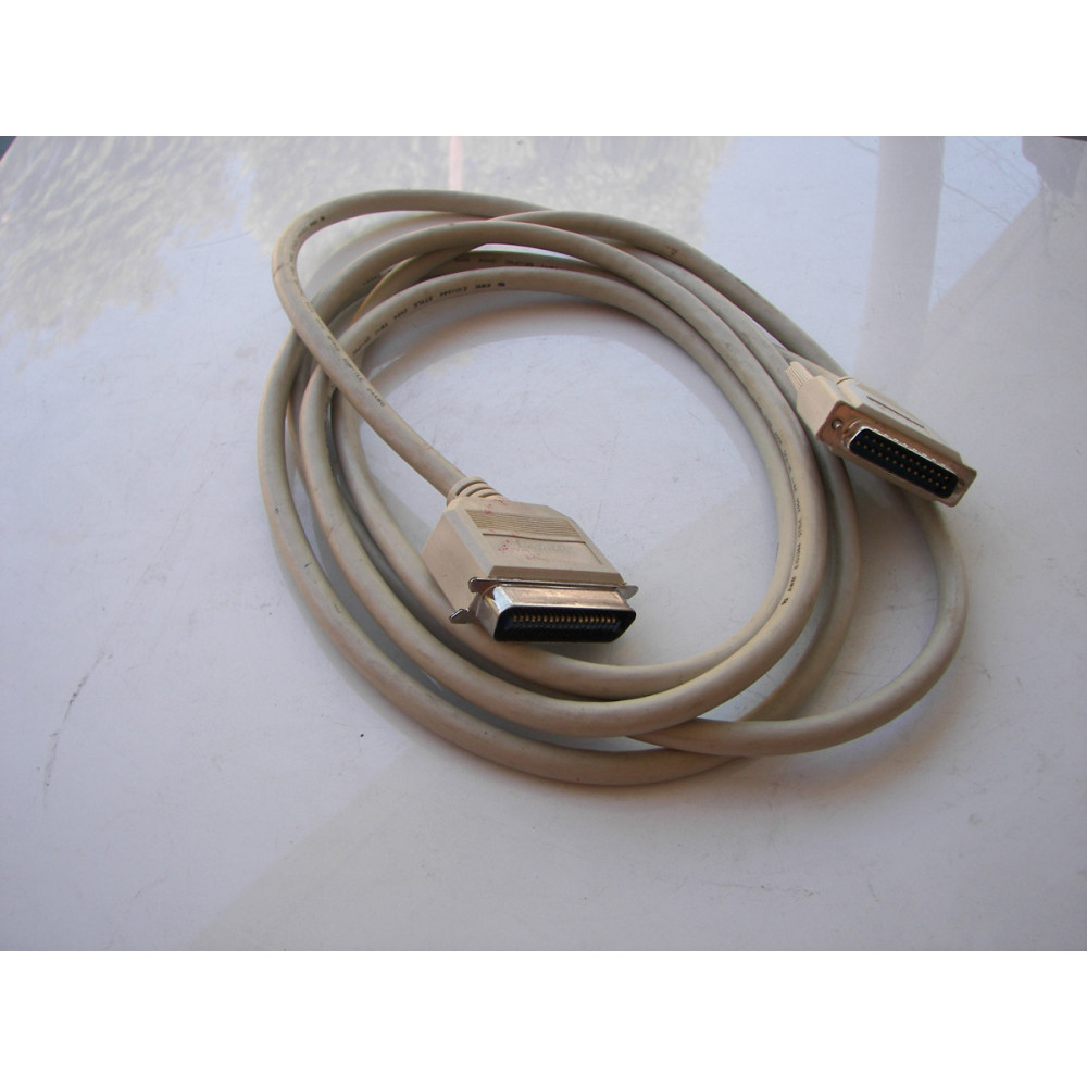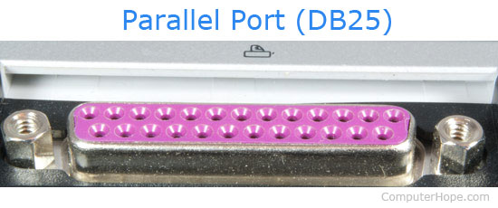

IEEE1284 standards for the cable, connector and electrical interface guarantee interoperability between all parallel peripherals, and ensure that data integrity is maintained, even at high data rates, at a distance of up to 30 feet.The Parallel ports Phil Storrs PC Hardware book The PC Parallel Ports The Parallel Port: The EPP and ECP modes both provide for bi-directional communication, with the assistance of additional hardware that generates and manages handshaking. This standard defines several modes of operation, including Compatibility mode, which allows data transfer in one direction only, Enhanced Parallel Port (EPP) mode, and Extended Capabilities Port (ECP) mode. The parallel port specification was formalised by the IEEE 1284 standard in 1994. Standard Parallel Port (SPP) Registers Register Offset The parallel port device registers occupy 3 bytes, beginning at the specified base address, and the bits in each register have specific signals associated with them, as shown in the table below. LPT1 is normally assigned base address 378h, while LPT2 is assigned base address 278h. It later reappeared as an option for an LPT base address. The 3BCh base address was originally used for parallel ports on video cards, and fell into disuse when video cards ceased to use parallel ports. The parallel port has three frequently used address blocks - 3BCh-3BFh (4 bytes), 378h-37Fh (8 bytes), and 278h-27Fh (8 bytes). Table 2.2.2 identifies the registers for the standard parallel port. Implementations of the parallel port that support the advanced modes of the IEEE1284 standard use 8 to 16 registers and are located at I/O addresses 378h or 278h or, in the case of a Plug and Play compliant parallel adapter, are re-locatable. These ports are referred to as the LPT ports and have the I/O base addresses of 3BCh, 378h and 278h. The registers are a block of 3 registers starting from the parallel port's base address. Insert a line feed for each carriage return.Ī low asserted pulse used to indicate that the lastĪ high signal asserted by the printer to indicate thatĪsserted low to indicate that some error conditionĪsserted high to indicate that the printer is online.Įach signal is assigned to a specific bit within the registers that make up the hardware/software interface to the parallel port. Used to indicate to the printer that it isĪctive low. Indicates valid data is on the data lines.Īctive low.

Standard Parallel Port (SPP) Signals GroupĪctive low. The table below identifies each of these signals, and gives their SPP definitions. Later implementations of the parallel port allowed data to be sent from a peripheral device to the PC. The data lines carry data from the PC to the printer, in one direction only. The status lines are used to send control signals and status information (for example, to indicate that the printer is busy or out of paper) from the printer to the PC.

In the original Standard Parallel Port (SPP), the control lines are used to send control signals from the PC to the printer. The signal lines are divided into three groups: The parallel port on a PC consists of a connector with 17 signal lines and 8 ground lines. The parallel port eventually evolved into the Enhanced Parallel Port (EPP), which allowed bi-directional communication, and a data rate of up to 2 Mbps in both directions, on cables up to nine metres in length. There was no standard for the interface, which made it difficult to guarantee correct operation on different platforms, and external cables were limited to two metres in length. Originally, the parallel port allowed for communication in one direction only (computer to printer), and the maximum data transfer rate was around 150 Kbps.


 0 kommentar(er)
